アルゼンチン旅行 '25 by Ryo
So I'm on somewhere above South America, back to the U.S. finished reading 社会学史. The book was great, as well as the trip which I will be writing about it later. The book gives you the overview of sociology, and it was just what I was expecting as I wanted to know about the kind of books I read and where my interest lies. Also it gave me some of topics and books that I didn't know about, and I'm thinking of looking into some of them. The first book is "客観性"論文, just because I like Weber. The second book is 現実の社会的構成―知識社会学論考, because 知識社会学 sounded interesting.
現実は、人間が解釈したり、意味を付与したりしなければ、現実にならない。ということは、社会的現実とは、人間の知識に媒介された構築物だということになります。このような現実の理解に立脚しているのが、バーガーとルックマンの"知識社会学"です - p455, 社会学史
Also for the reason where it says its a good introduction for those starting sociology, as I think I'm starting to enjoy sociology. It opens up the world a lot, and I'm excited about the world yet to be seen!
この本がとてもよい点は、まず、社会学理論や社会学史の勉強になるということです。いろんな学者の理論が出てきて、それらが、バーガーとルックマンの構図の中に、それぞれ位置づけられる。別の言い方をすれば、二人の構図は、さまざまな重要な社会学者の理論の張り合わせになっている - p456, 社会学史
The third book is 野性の思考. Its the same reason why I want to read 言葉と物 and 監獄の誕生.
当時支配的だった実存主義とマルクス主義 - とりわけ前者 - に対する解毒的な効果をもったということだと思います - p572, 社会学史
With that all being said, the last chapter on Structuralism was the most interesting I found among the all. It was mainly about Foucault and Luhmann. Maybe because I was interested in the subject back in my college days at first place for the reason ...
人間は、いまや"波打ち際の砂の顔のように消え去ろうとしている"という有名な句で、この本<言葉と物>を閉じています。このように書くとき、フーコーは、実存主義、とりわけサルトルの実存主義に引導を渡そうとしているのです - p578, 社会学史
... but I think its also because these days I'm interested in what is meant to be said by below.
Non ridere, non ligere, neque detestari, sed intelligere - スピノザ
Or in other words, if I understand correctly, can rephrased as below.
ルーマンの相対主義は、実践的には何を含意するのか。何もしない、というのが答えです。社会学ができることができることは、事態を記述すること - p566, 社会学史
Other than the reasons above, I'm interested in the book's approach of how it examines cases where we can find trace of エピステーメー. The book share examples of ラス・メニーナス and ドン・キホーテ, and I expect there to be more of such studies. Also, I leaned that there is a prison in Argentina which was designed to follow the logic of パノプティコン discussed in 監獄の誕生. May be I will visit the place if I get to visit Argentina for the next time haha.
Regarding Luhmann, I didn't know anything about him. But as the book suggests, how his theory gets along with Faucaut's sounds quite interesting ...
誰かの意識的な設計とか、意識的な計算とかには回収できない。そこにこそ、構造というもののふしぎがあるわけです - p519, 社会学史
... where it touches 構造主義のふしぎ just like how Faucault does, but in a different way.
ルーマンのオートポイエーシスの理論は...人間の意識的な統御の及ばない形でコミュニケーションは次々と接続され、自律的に形成していく...(構造主義の意味での)構造の生成の論理につながりうるものがある、と解釈できるのではないでしょうか - p552, 社会学史
Also, the discussion between Habermas and Luhmann ...
社会はそれ自体、社会の自己観察の産物として実在するというわけです...あらゆる社会にも通用する普遍的な真理などない、ということになります。どんなシステムにも成り立つような道徳的命題とか、正義という観念もここからは、出てこない...それぞれのシステムに相関かっこつきの真理や正義だけをみとめる、徹底した相対主義です。そうするとハーバーマスとの論争の意味もわかってきます...近代が未完だとされたのは...まさに現状を"未完"として位置づける完成した近代が、理想的な極点に想定されている。その極点には、普遍的な正義や真理が待っているのです - p566, 社会学史
... just reminds the discussion between Sartre and Foucault on 主体性, which also I think is quite interesting. Maybe I should take a look at 批判理論と社会システム理論 in regards. Related to the discussion so far, I remember Kant saying something about how our perception is limited by 理性. Its quite interesting how his discussion can be associated with those two. 純粋理性批判 might be interested to read given such context in mind.
根源的な構成主義は、カント以降の近代哲学のポテンシャルを徹底した結果だと言えます - p564, 社会学史
Another book I had been reading during the trip is ガルブレイス - アメリカ資本主義との格闘. I started reading the book as 消費社会の神話と構造 occasionally refers to Galbraith. The book discusses how American liberalism approach, which argues for free-market capitalism, is creating those issues in education, medication, retirement etc. Its a nice book with many insights. By looking at the gap we can see the issues America is facing today. Its something that we must think about.
アメリカの現実とかれの理想との間の開きは大きい。公共性の認識を強調する彼の文章からは、よき西欧を知ったアメリカ知識人の闘いを感ぜざるを得ないのである - p180, ガルブレイス - アメリカ資本主義との格闘
There is this uneasiness that I occasionally get when I'm in the country, and if I were to describe it after reading the book, it might be coming from me not fully convinced with ...
アメリカにはそうした<ヨーロッパのような>過去はない...成功するか否かは、自らの努力以外...に頼ることなく自らの足で立つ自立の考えが深く根ざしていたのである。それが、スペンサーの思想<社会ダーウィニズム>を広く受け入れさせた土壌であろう
... given that the growth which is supposedly promised with such American approach doesn't really seemed be working if I were to look around. Maybe I'll take a look at パワー・エリート along with ゆたかな社会 as the book suggests in p126.
生産量の増加させることは好ましいというかつての通念 - 経済学の中枢にあった考えで、アダム・スミスからはじまり、マルクスを含め今に流れる"生産優位"という考えは、疑わしいものになっている - p107, ガルブレイス - アメリカ資本主義との格闘
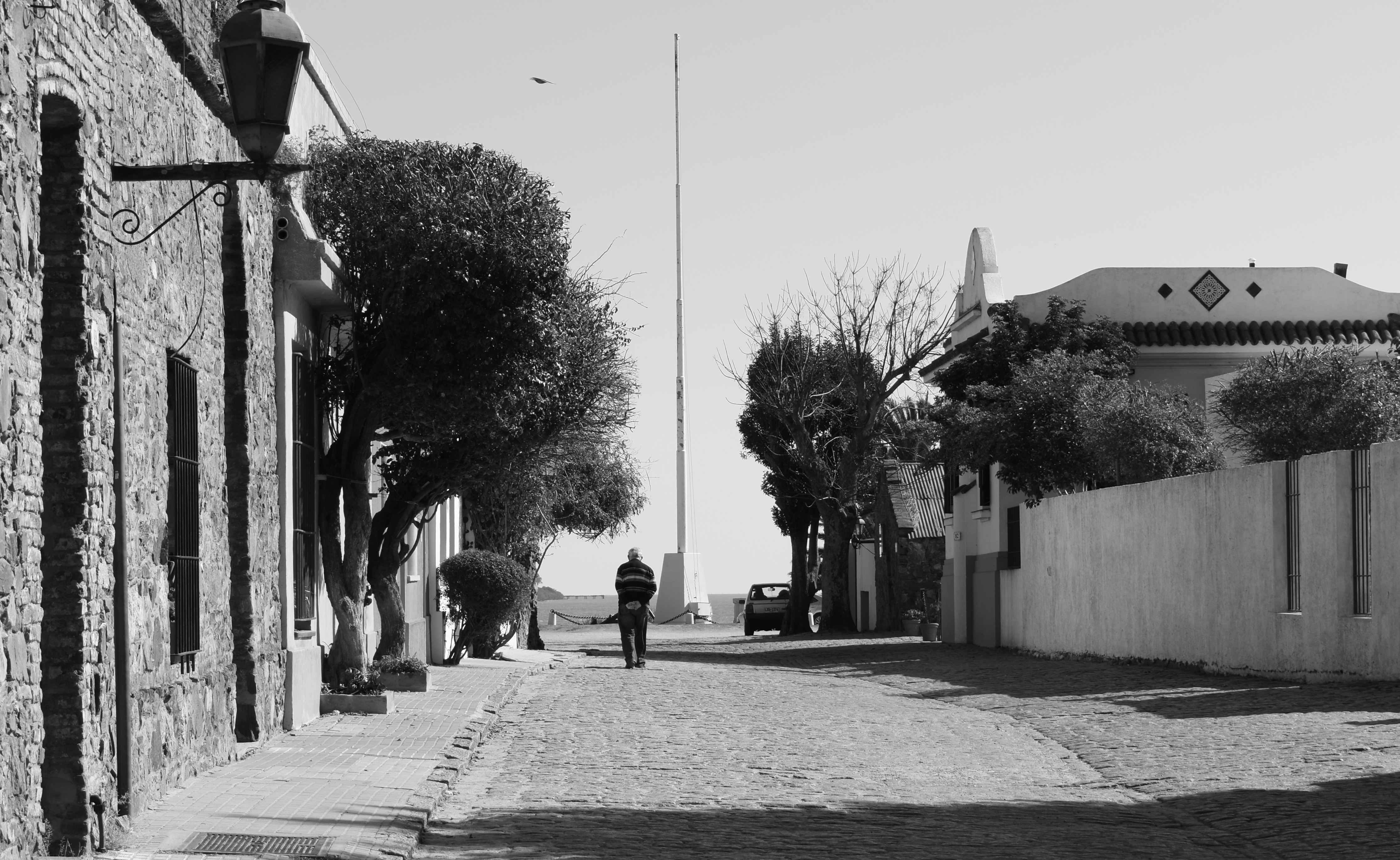
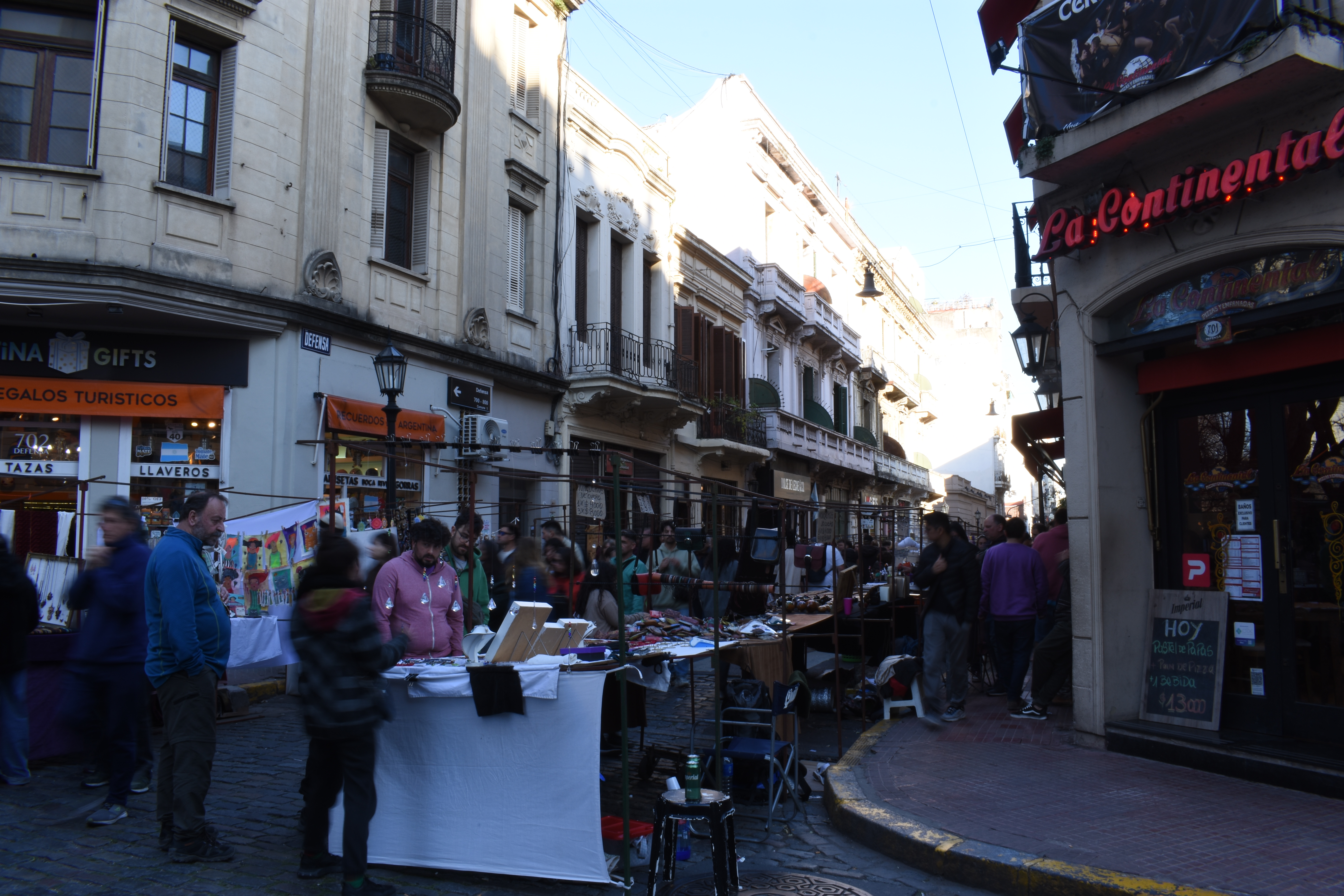
Enough about books, little bit about the trip. It was great. The city of Buenos Aires was beautiful and I enjoyed walking around [0]. I also went to Uruguay, and it was such a nice place to chill [1], and was so peaceful [2]. And as always, its nice to be back in America. It's the moment when I get back in Japan that I realize the country is my favorite, and start missing what I consider America, "America" haha. One thing that came as a surprise during the trip was the meal, Argentina is such a country with tasty food! I usually don't drink but this time I tried Malbec. My father told me this and that about wines while enjoying Bife de Chorizo😋. And mentioned this book, and the world sounds interesting. I might take a look into it.
Throughout the trip, I felt that we are all the same after all. Such differences like nationality, race, or language etc aren't that much of a difference. Its just that we live in a different society. It reminds me that what matters the most is to think myself and have my point of view ...
社会のさまざまな状況を現実的に、適応性を持って解釈する - 傷つきやすいアメリカの大学生たち
... and trips, and books of course, are great for taking a moment and reflecting on my interpretation of the world.
Colonia del Sacramento@Uruguay [2]
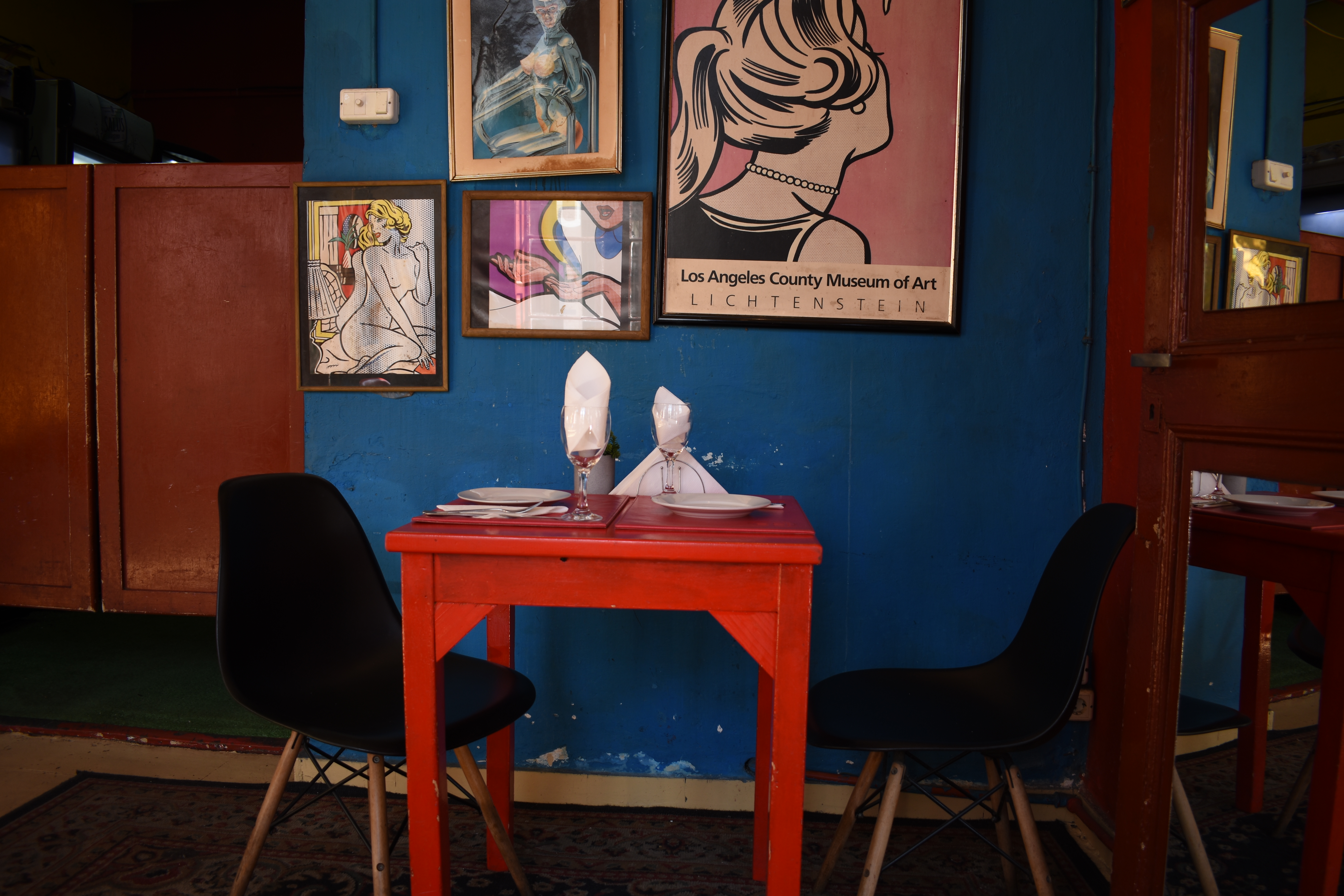
 Cafe@Colonia del Sacramento [1]
 And here is the physical setup and topology of my lab. I used two L2 switches to connect three routers and to prepare a local network for each of the routers.

 I recently took a simple benchmark regarding bandwidth and latency using this lab setup. It's great have an environment where you can gets your hands dirty😏. See you in the next post!
 First attempt, the pin for white/orange wire were not properly attached.
It is also not looking good as the cable sheet is too short for the plug😂.
First attempt, the pin for white/orange wire were not properly attached.
It is also not looking good as the cable sheet is too short for the plug😂.
 Second attempt, I misaligned the blue and white/green wire.
 Third attempt, I realized that I was configuring the order of the wires upside-down respect to the plug🤣🤣🤣.
 And here is the final product!
 Mistakes are proof that you are learning😎. See you in the next post!

 I have been interested in benchmarking my networking devices for a while and I am hoping to make a post about it within a next couple week. Anyways, see you in the next post!
 And here are some of the info on the hardwares that appear on the topology.
R1&R2: Cisco 892
VyOS: DELL Optiplex 3020
L3-1&L3-2: Catalyst 3560
L2-1&L2-2: Catalyst 2960
I'll be posting updates on my home lab whenever I learned anything interesting while working on it🧐. See you in the next post!
And here are some of the info on the hardwares that appear on the topology.
R1&R2: Cisco 892
VyOS: DELL Optiplex 3020
L3-1&L3-2: Catalyst 3560
L2-1&L2-2: Catalyst 2960
I'll be posting updates on my home lab whenever I learned anything interesting while working on it🧐. See you in the next post!